Design for Large / small / medium Office
DIAGRAM 1
- MIKROTIK Basic Configuration with Dual WAN Loadbalacing/Failover
- MIKROTIK for Network Office with Bandwidth and Application control
- MIKROTIK HOTSPOT SERVER for Guest and Authen with local user in mikrotik
Design for School / Hospital/ University
DIAGRAM 2
- MIKROTIK Firewall filter rule for control client (allow user can use ONLY service that specific such as HTTP, HTTPS, FTP, SSH)
- MIKROTIK NAT Section to Port Forwarding From WAN ip’s to Local Server and use src-nat to bind local server to route traffic via specific WAN IP
- MIRKTOIK Hotspot office user with Radius server (NPS on Active Directory)
- MIKROTIK PPTP VPN Server serve external client access to internal resource- Core Switch act Layer 3 for routing between each network of client (each vlan)
- Core Switch act DHCP relay for DHCP Server in DMZ Zone
- Syslog Thailand law
Design for Large scale Office / Hotel /Hospital
DIAGRAM 3
- MIKROTIK Dual WAN Loadbalacing with router bridge mode (recommend)
- MIKROTIK act layer 3 for routing communication between each network of client (each vlan)
- MIKROTIK Hotspot control for Guest user and authentication with radius server (RADIUS MANAGER DMAsoftlab)
- MIKROTIK Bandwidth and Application control
- MIKROTIK act DHCP server for give ip address to client
- Syslog Thailand law
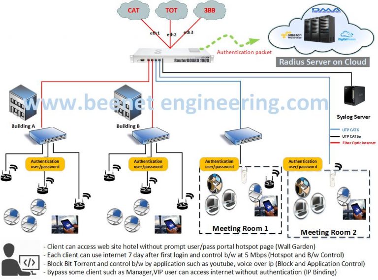
Design for hotels / apartment
DIAGRAM 4
- MIKROTIK Multi WAN Loadbalacing (WAN Different Type such as Static, DHCP Client, PPPoE)
- MIKROTIK Hotspot control authentication with radius server on cloud (RADIUS MANAGER DMAsoftlab)
- MIKROTIK allow client access web site without prompt user/pass portal hotspot page (Wall Garden)
- MIKROTIK bypass some client such as Manager,VIP user can access internet without authentication (IP Binding)
- MIKROTIK Bandwidth and Application control such as youtube, facebook, voice over ip
- Syslog Thailand law
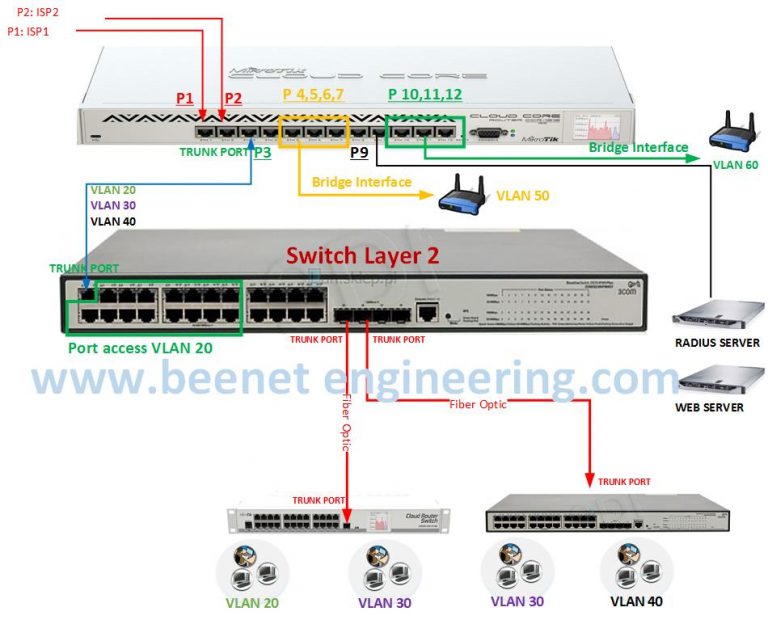
Design for School / Hospital
DIAGRAM 5
- MIKROTIK and Manage Switch Layer2 solution
- MIKROTIK Dual WAN Loadbalacing
- MIKROTIK MIKROTIK act layer 3 for routing communication between each network of client (each vlan)
- Core Switch act Layer2 (VLAN)
- Dirtribute switch act Layer2 (VLAN)
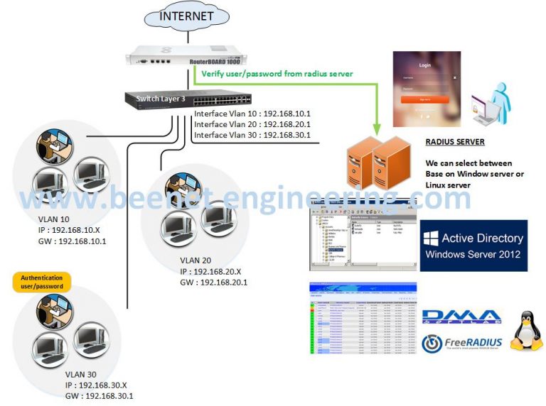
MIKROTIK and Manage Switch Layer3 solution
DIAGRAM 6
- Core Switch act Layer 3 for routing betweeen each network of client (each vlan)
- User and Guest nust authentication with Radius Server
- Radius Server with NPS that verify account form
- ACtive Directory on Window 2012 Server
- Radius Server with freeradius on Linux (DMASoftlab)
Centralized RADIUS and Multiple Mikrotik
DIAGRAM 7
- ในกรณีที่มีโรงแรม ที่มีสาขาหลายๆสาขา สามารถติดตั้งระบบในรูปแบบนี้ได้ จะทำให้ระบบถูกรวมศูนย์และบริหารจัดการได้สะดวกยิ่งขึ้น
- ป้องกันปัญหา single point of failure ถ้าหากใช้ mikrotik ในการจัดการคูปอง ด้วยตนเอง ทั้งนี้ที่ radius server จะมีการสำรองข้อมูลทุกๆวัน
- ลงทุนแค่ครั้งเดียว ประหยัดค่าใช้จ่าย และ รองรับการเติบโตในอนาคต หากมีโรงแรมหรือคอนโดสาขาเพิ่มในอนาคต
